The Willett Cathodic Protection Rectifier is a light, rugged, one-piece aluminum enclosure with a removable back panel that provides corrosion protection by way of sacrifical anodes. Features include universal pole or wall mount; continuous reading internally shunted Ammeter and voltage meter; lightning arrestors on A.C. input; M.O.V. type surge protection on D.C. output; magnetic trip circuit breaker and fuse provide overcurrent and short circuit protection.
The Willett standard air cooled transformer tap adjustment rectifier is for use on an A.C. source power supply to provide D.C. current for Cathodic Protection.Required Safety Standard
All transformer rectifiers shall meet or exceed the requirements of the Canadian Standards Association (CSA)standard C22.2 No. 1-7-1957 (R1967)Rectifying Equipment. Customers in which the CSA standard is not recognized in their country can contact the factory to adjust for specific standard specifications.General Specifications
A.C. Input:Full rated D.C. output is obtainable with input voltage 5% below the nominal value. Continuous input voltage 10% above the nominal value shall not damage the transformer or rectifying elements or exceed component ratings.
D.C. Input:Standard rectifiers of the air cooled variety supply continuous full rate output at 5% low line voltage and at an ambient temperature of 45° C in full sunlight with an expected life in excess of ten (10) years.
Type:Fully isolated primary and secondary windings are accessed by wire tap tails which lead onto respective terminal blocks.
Primary leads (dual voltage) normally terminate along with the lightning arrestor leads in a terminal block accepted for dual conductor entry. Appropriate shielding is provided over the terminal block to prevent contact with hazardous live parts.
Nine secondary tap settings (4 coarse – 5 fine) provide 20 equivoltage increments over the full transformer output range. The secondary terminal strip is of the tubular screw type complete with pressure plate and is mounted on a channel above the transformer core. These terminals are also shielded if output voltages exceed 30 VAC or 42.V D.C.
All materials are capable of withstanding 2250 volts (RMS at 60 Hz) applied for one minute between the windings and between the windings and the core. Transformer magnet wire and insulation materials shall be rated for Class H operation (180° C). This insulation shall be enhanced by dipping in thermosetting varnish and baking. The varnish shall exceed CSA C22.2 No.D for Class H operation.
Sleeving used for tap lead wire insulation within the winding will have a dielectric breakdown strength of not less than 5,000 volts average and will meet the requirements of CSA, NEMA, and BSI with respect to heat aging. Only flexible 105° C, 600V rated wire is used; (i.e. Neoprene motor lead).
Transformer lead wire and terminal blocks shall be sized at a minimum 500 circular mils per amp, silver soldered to coil at termination points. Internal transformer joints are taped with a fiberglass ribbon and isolated from other turns by varnish cloth patches.
Transformer coils shall have a minimum 800 cm/amp guage wire sizing. This increases as well in larger sized transformers.
The transformer voltage regulation is not to exceed 3% from full-rated load to 1/2 of rated load when measured in accordance with the procedure described in MR-20-1958 or equivalent. Minimum transformer efficiency allowable is 95%.
The core shall be constructed from high grade, grain oriented steel laminations with a maximum thickness of 26 gauge. The transformer shall be designed for a maximum FLUX desity of 9 Kilogauss. The core shall be EI type laminations secured to and mounted by die stamped mounting legs.
The magnetic core losses must not exceed .83 Watts per pound for 26 gauge material at 60 Hz when tested in accordance with ASTM Specification A-34 or equivalent.
The elements of the full wave bridge rectifier are silicon diode packaged either in molded bridges or, for the larger sized, as discrete devices mounted in a standard extruded aluminum heatsink and wired to give the same configuration.
Assembled stacks can be subjected to 2,000 volt, 60 Hz AC, applied between each of the power terminals and molded casings, or in the discrete diode case, between each of the dielectric terminals and the mounting studs.
Diodes are rated to provide an adequate margin for over-voltage surges and over-current surges. A 600 peak reverse voltage (PRV) rating is minimum for all diodes used in the power circuit. In the next regard, all stacks are rated a minimum 50% above the rated output current and have thermal dissipation capabilities likewise allowed, therefore, diode junction and case temperatures in the continuous full load case are well below the maximum temperature recommended by the manufacturer.
In addition, all single phase bridges are protected by a metal oxide varistor (MOV) designed to clamp over-voltage surges.
Proper secondary fuse protection is also very important to semiconductor logevity. The semiconductors of the bridge are over-current protected by a very fast acting semiconductor protection fuse in the rectifier circuit.
This special fuse is rated as close as practicable to the full load transformer secondary requirements thereby providing the necessary overload and short circuit protection.
All current carrying conductors (studs included) shall provide a minimum cross sectional area of 0.26 mm (500 circular mils) per ampere of current for the full rated rectifier output. Conductor insulations are a minimum 90° C rated and of rubber thermoplastic or neoprene arranged neatly in wiring harness fashion and of proper length to avoid tension at terminals.
D.C. Terminals are located convenient to the cable entry and are of the high strength aluminum alloy solderless pressure type lug. These lugs are CSA approved for applications with either copper or aluminum conductors.
| CIRCUIT CURRENT RATING (A. DC) Less than 12 |
TERMINAL AWG
|
SIZE METRIC
|
D.C. terminals are clearly labeled positive and negative.
The D.C. output terminals are secured to the insulating phenolic instrument mounting board by silicon-bronze alloy all thread bolts (ANSI B18.2.1[R1970]) appropriately supplied with lock washers and double nutting around each electrical eyelet connector terminal and immediately around the phenolic instrument board.
For units rated 30 VAC or 42.4 VDC and above the DC output terminals are mounted to the phenolic mounting board and covered by a lexan Plexiglas barrier. This is a CSA requirement whereby all live parts must be suitably covered preventing open access
A.C. terminals, insulated sufficiently to withstand 8,000 volts to the enclosure, shall be shielded to prevent accidental contact and will be sized to take cable sized #14 through 1/0 AWG (2.5 to 50 in metric sizes).
A.C. terminals are clearly labeled.
All wire junctions are made using crimp-on terminal lugs, mechanical lugs, screw terminal and wire clamp or conducting nut and bolt type electrically approved terminations. All connections shall be mechanically secure and electrically continuous.
Separate, continuous reading internally shunted volt and ampere meters are provided for monitoring the rectifier output.
Meters are of molded phenolic construction with optically clear acrylic fronts sealed so as to retard corrosion.
Rated rectifier output is not to be less than 70% of full scale. All scale divisions have even units, directly readable in volts or amperes. Meters are the 6.3 cm, (2.5 inch) nominal size or larger and of an open scale design with tapering knife edge pointers to provide maximum readability.
Highly reliable in-line measurements of major and auxiliary current are the function of the provided ammeters. D.C. voltage measurement shall be taken directly accross the stack output thereby reflecting the major circuit potential difference.
Meters are accurate within 2% of full scale at 25° C and possess temperature stablility of at least 1% per 5° C deviance for the -40° C to +75° C range.
An automatic operating device preventing dangerous apparatus temperatures or short circuit events is provided for each ungrounded conductor of the supply. This breaker is of the fully magnetic type and is situated as the first termination of the incoming AC power thereby also serving as a manual on/off disconnect for the rectifier.
Reliable tripping of a fully magnetic breaker is typically 115% of its rating. Beneficial features of the fully magnetic breaker include:
Instantaneous tripping caused by excess leakage flux in the magnetic circuit as a consequence of high transient fault currents
Common series tripping of two pole breakers of 480 VAC maximum voltage per pole rating is standard.
General breaker ratings are 1.5 x maximum low line input current.
Secondary Circuit ProtectionVery fast acting fuse design for the protection of semiconductors are used in protection of the transformer secondary and diode bridge. These fuses shall be sized as close as practical to the full load low line current requirement of the A.C. transformer secondary (12% typical). The fuses are mounted in approved bakelite or phenolic holders.
Suitable lightning arrestors will be installed on both the A.C. and D.C. sides of the unit. Silicon oxide varistors (SOV’s) are employed with 600 volt and 100 volt ratings for A.C. and D.C. operation respectively. Spark-over voltages allowed on these units are respectively 1000 and 500V. Small energy metal oxide varistors (MOV’s) are provided as well on the rectifier bridge A.C. inputs.
Enclosures will be resistant to warpage and weathering and made of incombustible corrosion-resistant material.
All materials are Aluminum sheet or galvanized hardware.
Quick removal instrument back panel complete with lightning arrestor, transformer, bridge and secondary fuse, mounted to the left side of the raised phenolic instrument panel.
When required in a dual circuit model, a rheostat (.5 ohm, 150w) is mounted to the steel work supporting the phenolic instrument panel.
Instrument panel shall be 1/4″ black matte finish grade XX reinforced
Sturdy, boltable and padlockable over center latch for securing door.
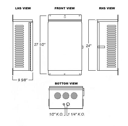
Ventilation screening on the enclosure bottom; 1/8″ hole perforated sheet steel in 3/16″ staggered pattern is used.
Mounting strips along top and bottom permit universal pole/panel mounting.
Two press-formed knockouts in the bottom panel provide convenient access for incoming A.C. supply (3/4″) and out-going D.C. cathodic lines (1″ trade size).
Full length aluminum piano hinges are provided on the front door.
CEMA 3R cabinet complete with high density weather stripping around inside of door.
Pamphlet holder 10″W x 5″H is provided with each unit mounted to the inside of the door.
A grounding lug is provided inside the enclosure. Similarly, a #6 AWG rated grounding lug is provided on the outside of the cabinet for grounding protection as required. In both cases, electrical continuity is assured through use of locking washers, 10/32″ tapped screws and grinding paint from the contact surface of the lug.
A permanently stamped metal foil plate will be attached to the inside of the door with the following information:Manufacturer
Model Number
A.C. Volts
A.C. Frequency
Phase
Maximum Input Current (A A.C.)
Maximum Total Output Current (A D.C.)
Rated Output Voltage (V D.C.)
An English only technical manual is provided giving important, relevant information on rectifier particulars.
A serial number is also applied to each unit.
Units are individually packaged in cardboard boxes. Numerous units are banded together on a standard size shipping pallet.
Dielectric testing per CSA C22.2 No. 107Transformers individually, and assembled rectifiers complete.
Output testing per CSA C22.2 No. 107 plus Willett QMI standard procedures:Input, output power at 0.50% and 100% and 115% load.
Meter readings vs. shop instrument readings
In addition, Willett’s QMI procedures call for routine visual and performance testing by management and sales.
A record of all tests shall be included with each rectifier.
All equipment or apparatus is guaranteed against defective materials and/or workmanship for a period of one year from date of shipment.